Brief Introduction
The functionality of ASoC (ALSA System on Chip) has been subdivided into the following components:
- Platform class driver: This defines the SoC audio interface for the CPU itself, encompassing both the Digital Audio Interface (DAI) and any potential audio multiplexers (e.g., i.MX8 has its IOMUX).
- CODEC class driver: This manages the actual CODEC device.
- Machine drivers: These serve as the intermediary between the SoC and the CODEC, bridging both interfaces. However, writing a separate driver for each SoC-CODEC combination poses scalability challenges.
In contemporary setups, many CODEC class drivers are now configured using a simplified audio-card description in a device tree, effectively replacing the need for machine drivers.
The objective of this article is to outline my efforts in configuring the TLV320AIC3204 codec to function with the I.MX8MP platform.
General
The setup of the CODEC typically occurs on an I2C bus, although simpler buses like SPI could also be utilized. While configuration data is transmitted via this straightforward bus, the audio data is conveyed through a separate bus altogether.
Audio data can be transmitted in various formats such as TDM, PCM, or I2S.
In order to abstract this bus and manage it uniformly, we refer to it as DAI, representing Digital Audio Interface.
Different System-on-Chips (SoCs) employ varying terminology for this interface. For instance, Texas Instruments utilizes McASP, NXP employs SSI, Atmel uses SSC, and so forth. However, we consistently refer to it as DAI across the board.
Serial audio formats
I2S
I2S, a prevalent 5-wire Digital Audio Interface (DAI) commonly employed in embedded systems, utilizes TX (SDOUT) and RX (SDIN) lines for audio transmission, while bit and frame clocks synchronize the data.
Key signals include:
- Master clock or system clock, often denoted as MCLK, which serves as the primary clock source for deriving other clocks and drives the CODEC.
- Bit clock, also known as BCK or BCLK, whose frequency varies based on the sample rate.
- Frame clock, alternatively referred to as LRCLK (Left-Right Clock), FCLK (Frame Clock), or WCLK (Word Clock).
- Audio out, denoted as SDOUT.
- Audio in, labeled as SDIN.
The relationship between BCLK and LRCLK is expressed as:
bclk = (sample rate) * Nchannels * (bit depth)
Certain CODECs have the capability to utilize BCLK as their sole clock, rendering MCLK optional. The chosen CODEC accommodates this feature, necessitated by hardware constraints limiting available signals that can fit into a connector.
According to the datasheet, the maximum rise and fall time for BCLK can reach up to 10 ns, provided that the high and low periods of BCLK exceed 50 ns.
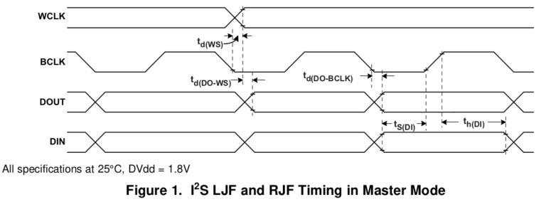
I2S can be employed with Time-Division Multiplexing (TDM) format timing to accommodate additional audio channels on the same I2S bus. In this configuration, the timing appears as above
Facing challenges with ASoC configuration, codec bring-up, or clocking on i.MX8 platforms?
TDM
Time-Division Multiplexing (TDM) is a technique utilized in certain audio interfaces, such as I2S, to transmit multiple audio channels within a single data stream.
PCM
PCM (Pulse Code Modulation) is a 4-wire interface that shares similarities with I2S.
Clocks
In our setup, we have multiple clocks including the bit clock, frame clock, and master clock. The responsibility for generating these clocks is flexible and can be determined based on our requirements.
Typically, either the System-on-Chip (SoC) or the CODEC can generate some or all of these clocks, a configuration referred to as clock master (e.g., bit clock master or frame clock master).
While it’s usually simpler to let the CODEC handle the generation of all clocks, certain SoCs offer specialized audio PLLs for this purpose. However, in our scenario, the SoC will serve as the clock master.
The Hardware
The SoC
The board selected for our project is an evaluation board designed for the i.MX8MP processor, running with Android 13. This CPU module boasts support for five I2S buses, and for our application, we will utilize one of these buses.
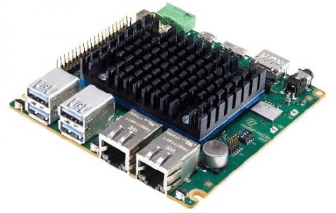
Pic Courtesy – https://www.tq-group.com
The CODEC
We have chosen the TLV320AIC3204, manufactured by Texas Instruments, as the CODEC for our project.
The TLV320AIC3204, also known as the AIC3204, is a versatile stereo audio codec characterized by its flexibility, low-power consumption, and compatibility with low-voltage environments. It features programmable inputs and outputs, Power Tune capabilities, fixed predefined and parameterizable signal-processing blocks, an integrated PLL, integrated LDOs, and flexible digital interfaces.
For configuration, the AIC3204 employs the I2C interface.
In our setup, we will utilize the AIC3204 with I2S in Time-Division Multiplexing (TDM) mode as the Digital Audio Interface (DAI), and the I2C interface for configuration purposes.
The Software
As we have transitioned away from relying heavily on machine drivers and now have the capability to describe CODEC bindings using the device tree, configuring the system primarily involves writing device tree entries rather than C code.
To set up the sound card, we utilize the device tree node called “simple-audio-card”.
SAI node
The Synchronous Audio Interface (SAI) module is a hardware component of the i.MX8 System-on-Chip (SoC) responsible for generating digital audio signals.
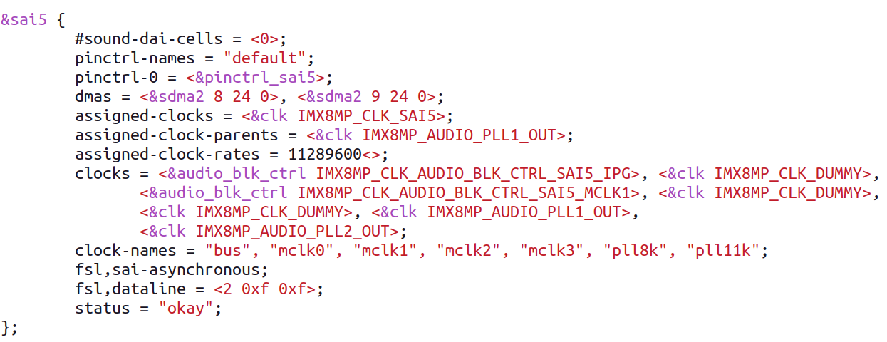
In our configuration, we will utilize the SAI5 interface, which is routed from the i.MX8MP module. The necessary configuration for this interface is already defined in an interface (.dtsi) file. Therefore, our task involves enabling the SAI5 interface.
					&sai5 {
    status = "okay";
};
Sound node
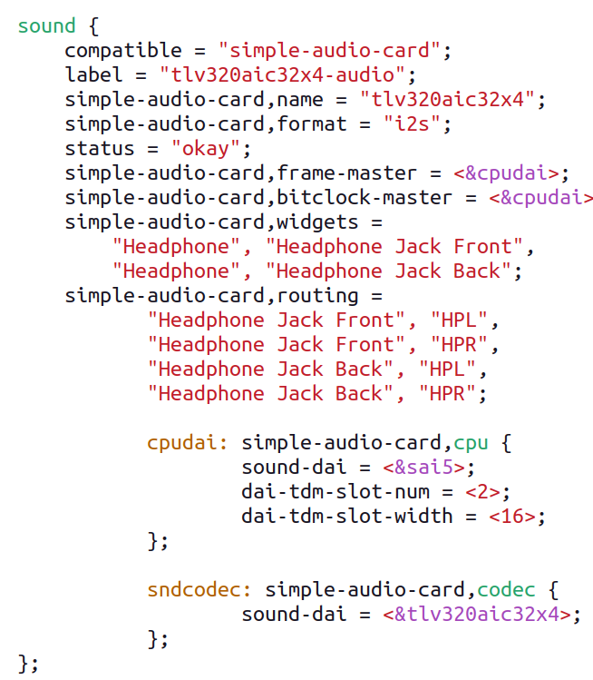
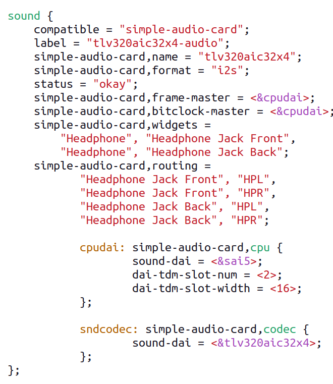
It’s now time to configure the sound node. Here’s how we proceed:
- Specify the audio format by setting the “simple-audio-card, format” property to “i2s”.
- Set up the two Digital Audio Interfaces (DAIs) we are going to use (CPU and CODEC) by creating sub-nodes and referring to the SAI module CPU node and CODEC node as “sound-dai” respectively.
- These sub-nodes are referenced when assigning “frame-master” and “bitclock-master” properties in the sound node. Since we want the SoC to generate both frame and bit clocks, we set “cpudai” as the clock master for both.
By following these steps, we ensure that the sound node is properly configured for our setup.
CODEC node
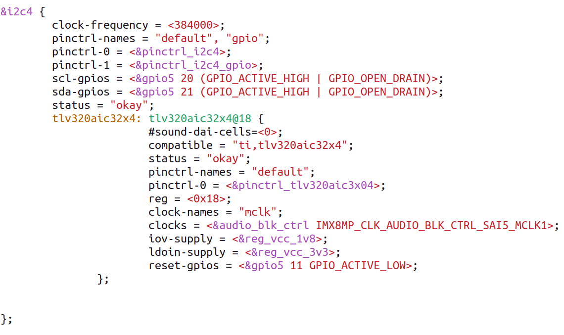
To configure the TLV320AIC3204, which is connected to the I2C4 bus and responds to the slave address 0x18, we need to define a codec node as a sub-node of the I2C node in the device tree.
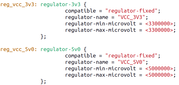
In addition to the “compatible” and “reg” properties, the codec node requires phandles for a 3V3 supply that powers the digital circuitry and another phandle for the Class-D amplifier and analog part.
Since our hardware lacks controllable supplies for these components, we must create fixed regulators for them.
The TLV320AIC3204 is connected to the I2C4 bus So, we are placing CODEC node as a sub node of I2C node.

Kernel set up:
To interface the TLV320AIC3204 with the i.MX8MP, it’s necessary to enable the driver of the CODEC in our defconfig file.
In our case:
					CONFIG_SND_SOC_TLV320AIC32X4=y

CONFIG_SND_SOC_TLV320AIC32X4_I2C=y
Sound test
Now that everything is properly configured, let’s proceed with testing our setup using tinyplay, which is similar to aplay for Linux, and is part of the alsa-utils package.

It seems there was an issue due to the sample rate mismatch. To address this, we need to ensure proper clock setup.
Debug clock signals
Let’s look what our clock tree looks like:
evk_8mp:/ # cat /sys/kernel/debug/clk/clk_summary
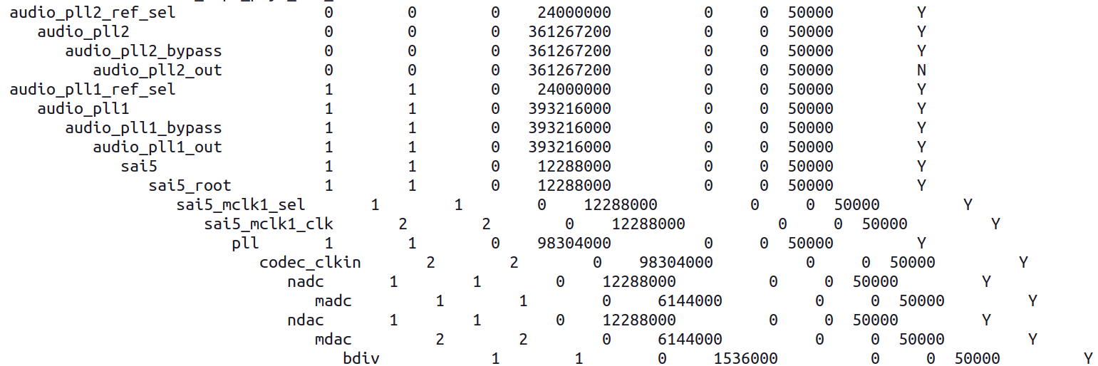
It appears that the SAI5 clock is running at 12,288,000 Hz, which makes it challenging to find a suitable clock divider for achieving a 44 kHz sample rate. Instead, we can consider using the audio_pll2 clock at 361,267,200 Hz, which provides a better match. With this clock, the calculation ((361267200 / 44100) / 256) yields a value close to 32, which is almost perfect for achieving the desired sample rate.
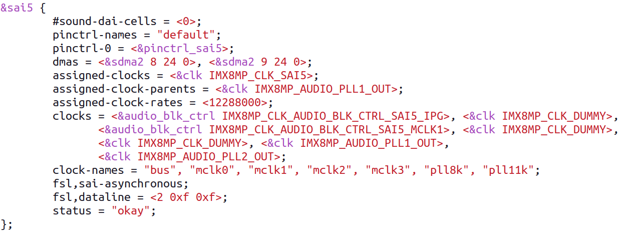
To reparent the SAI5 module to use the audio_pll2 clock, we need to make adjustments in the device tree.
Pin control of SAI5:
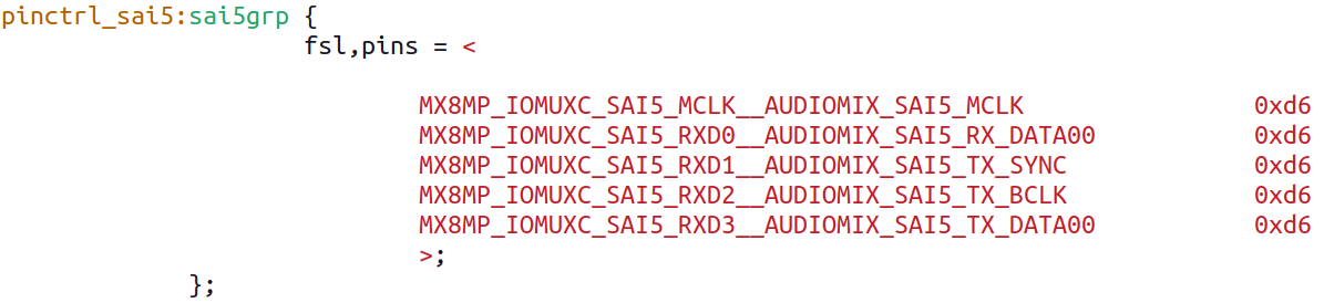
Here is our new clock tree:
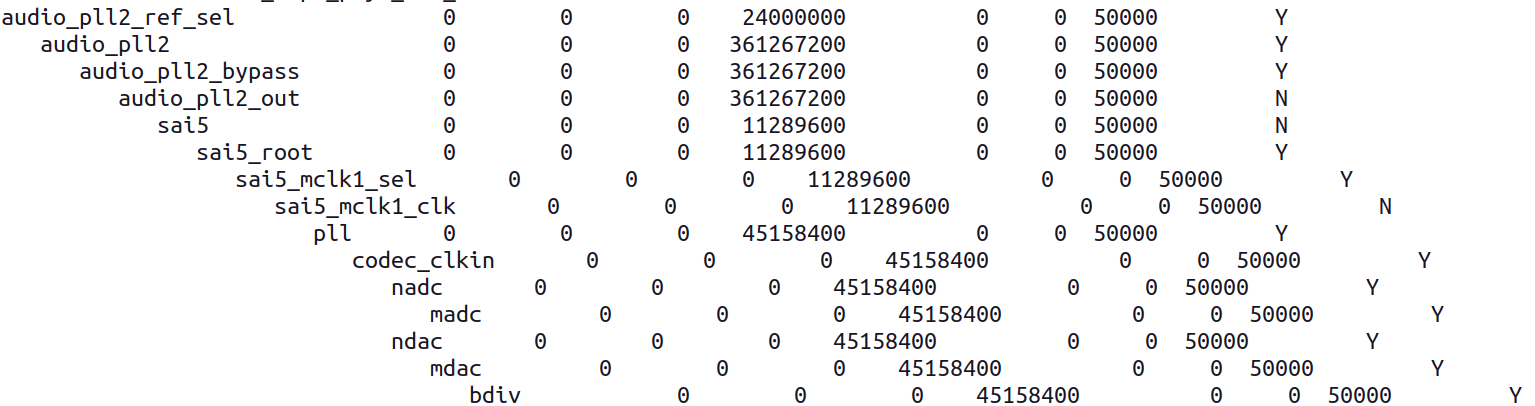
We can see that the frequency is right and also that we now derive our clock from audio_pll2_out instead of audio_pll1.
The tinyplay software is also happier and running:
To reparent the SAI5 module to use the audio_pll2 clock, we need to make adjustments in the device tree.

Unfortunately, I am not able to hear sound in headphone or speaker, So, I need to set the tinymix.
Let’s see what our tinymix is:
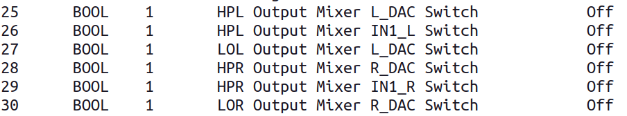
Here, our output switches are OFF, so we need to configure it as ON.
To configure it use this command: tinymix <switch number > 1(ON) or 0(OFF)
Eg: tinymix 25 1
After turning it ON you can be able to hear the sound
Building production-ready Android audio on custom hardware?
Use BCLK as MCLK
Considering the hardware constraints, you need to use the bit clock as the master clock. Referring to the datasheet for guidance is a prudent approach.
Digital Audio IO Interface
Based on the provided information, the audio data transmission between the host processor and the TLV320AIC3204 occurs via the digital audio data serial interface, also known as the audio bus. This bus offers flexibility with options such as left or right-justified data formats, support for I2S or PCM protocols, programmable data length settings, TDM mode for multichannel operation, and configurable master-slave configurations for each clock line. Additionally, it allows direct communication with multiple devices within a system.
The TLV320AIC3204’s audio bus can be configured for left or right-justified, I2S, DSP, or TDM modes of operation. These modes are all MSB-first, with the data width programmable as 16, 20, 24, or 32 bits. The word clock and bit clock can be independently configured in either Master or Slave mode for flexible connectivity to various processors. The word clock marks the beginning of a frame and can be programmed as either a pulse or a square-wave signal. Its frequency corresponds to the maximum of the selected ADC and DAC sampling frequencies.
If the BCLK to LRCLK ratio is 64, it’s possible to connect MCLK directly to BCLK. However, since our BCLK is 1,411,200 Hz and the LRCLK is the same as the sample rate (44 kHz), this ratio is not 64.
While the frame clock (LRCLK) sticks to the sample rate, utilizing TDM can enable the bit clock to run faster with the same frame clock. Let’s consider adding 2 TDM slots with a 16-bit width to achieve this.
Following the modifications mentioned above, sound playback is operational at the kernel layer, yet remains inactive at the framework and application layers. To enable sound playback at these levels, further adjustments are required within the Hardware Abstraction Layer (HAL).
HAL layer:
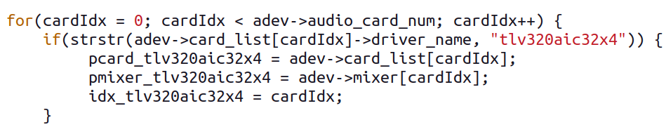
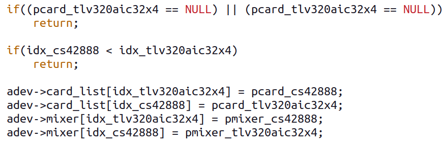
We have to make changes in tinyalsa_hal.cpp file as below:

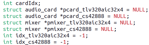
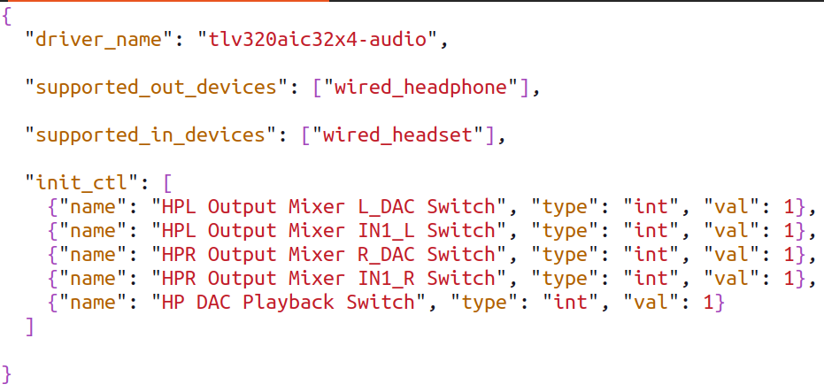
Here, I am using android 13 so, whatever we were doing manually with tinymix, that we can add here in /device/nxp/common/audio-json/<name of CODEC.json> file. It will turn all the switches ON at boot time.
Now we are good to go for playing sound from application layer.
I play sound from device but getting error as shown below:

To require this sample rate, we must update .dts again.
Now it is working perfectly.
Final device tree setup


Conclusion
The utilization of the “simple-audio-card” method offers a versatile means of delineating audio routing. I ardently advocate for this approach over the necessity of crafting individual machine drivers for every SoC-CODEC configuration.
Furthermore, “simple-audio-card” facilitates intricate setups encompassing multiple DAI links.
