Introduction
Read more about our upstream contributions for i.MX8. Click here.
Explore the journey of Silicon Signals’ board bring-up and hardware upstreaming experience here.
Hardware Design Flow
In the realm of electronics, every design undergoes a structured progression:
Initially, the Hardware and Software teams collaborate to conceptualize the system design. Subsequently, the hardware design team commences their work, translating these ideas into reality.
The hardware designers craft the schematic and layout files, which then proceed to fabrication and assembly houses for proto-creation.
At the culmination of the Hardware team’s efforts, the tangible physical hardware emerges.
What Is Board Bring-Up?
However, upon its arrival, the hardware remains lifeless, existing merely as a bare PCB devoid of any operational software or validation.
At this juncture, software engineers and hardware engineers once again unite their expertise to breathe life into the hardware. This pivotal phase is referred to as board bring-up, essential for the validation and functionality of any hardware electronics design.
Board Bring-Up for NXP i.MX8MM Hardware
Performing board bring-up for an NXP-based i.MX8MM hardware entails a methodical approach:
1. Initial Analysis by Hardware Team:
The hardware is handed over to the hardware team for thorough scrutiny. This involves:
- Visual Inspection and Mapping: Comparing the physical board with the schematic and layout to identify any discrepancies such as missing components.
- Impedance Measurement on Power Rails: Ensuring power integrity by measuring impedance on power rails.
- Component Shoulder Quality Validation: Assessing the quality of assembled components to detect issues like dry soldering or pin shorting.
- Power Application and Measurement: Applying power to the board, checking ESD protections, and measuring signals to verify functionality.
2. Power-On and Initial Boot:
- Once validated, the board is powered on, and initial boot-up sequences are observed.
- Boot-up logs and serial console outputs are monitored for any errors or abnormalities.
3. Functional Testing:
- After successful boot-up, functional testing of various subsystems and peripherals is conducted.
- This includes testing interfaces like USB, Ethernet, HDMI, etc., and verifying their functionality.
4. Software Validation:
- Software engineers work alongside hardware engineers to load initial firmware or operating systems onto the board.
- The software is validated to ensure proper interaction with the hardware and functionality of essential features.
5. Debugging and Issue Resolution:
- Throughout the process, any encountered issues are meticulously debugged.
- Debugging tools such as oscilloscopes, logic analyzers, and JTAG debuggers are utilized to identify and resolve hardware and software issues.
6. Documentation and Reporting:
- Comprehensive documentation of the board bring-up process, including findings, debug steps, and resolutions, is maintained.
- Reports summarizing the board’s functionality, identified issues, and resolutions are generated for reference.
By following these steps, the hardware team ensures a systematic and thorough board bring-up process for NXP i.MX8MM-based hardware, resulting in a validated and functional system ready for further development and integration.
Struggling to turn complex hardware into a stable, production-ready system?
Flashing Validation
The next step after board bring-up is flashing validation, which involves verifying the capability of the hardware to accept and flash firmware onto it.
In the case of IMX8 series hardware, NXP offers Boot mode switches to enable different modes of operation.
However, considering that we’re dealing with a custom board, relying on NXP’s prebuilt images might not suffice. Customization is necessary to tailor the firmware to meet the specific requirements of the custom hardware.
To proceed with flashing validation:
1. Put the Hardware into Serial Downloader Mode:
- Utilize the DIP switches provided by NXP to configure the board into serial downloader mode. This mode facilitates direct communication with the bootloader for flashing purposes.
2. Utilize UUU Utility for Validation:
- Employ the Universal Update Utility (UUU) to ascertain whether the hardware chipset is recognized and available for flashing the new firmware.
- UUU is a versatile tool commonly used for flashing firmware onto NXP i.MX series devices.
3. Customization for Custom Hardware:
- Given the bespoke nature of the hardware, it’s imperative to customize the firmware to align with the specific requirements and interfaces of the custom board.
- This may involve adapting device tree configurations, bootloader parameters, and other settings to ensure compatibility and optimal performance.
By executing these steps, we can validate the flashing capability of the custom hardware, ensuring that it’s primed to accept and execute the tailored firmware, thereby enabling seamless integration and functionality.
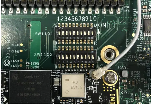
Reference image courtesy – imx8m evk from www.nxp.com
Preparing for BSP Customization
To better understand the hardware and expedite the customization process, it’s essential to gather pertinent
documents provided by the System-on-Chip (SOC) vendor.
1. Collect SOC Vendor Provided Documents
- Obtain documentation such as datasheets, reference manuals, application notes, and any other relevant
materials provided by the SOC vendor. These documents offer insights into the architecture, features,
and specifications of the SOC.
2. Reference BSP Setup
- Acquire the reference Board Support
Package (BSP) from the SOC vendor and set up the Evaluation Kit (EVK) corresponding to the SOC.
This facilitates familiarity with the SOC’s capabilities and functionalities.
3. Build Custom BSP using EVK
- Utilize the reference BSP and EVK setup to establish a baseline for customizing the BSP according to the
requirements of the custom hardware
design. - Connect desired peripherals to the EVK to emulate the configuration of the custom hardware and iterate
on the BSP customization process.
4. Utilize Available References
- Refer to the schematic and layout of the custom hardware design to understand its architecture and
component interconnections. - If schematic and layout files are unavailable, resort to older BSP versions or device tree
configurations for reference.
5. Extract Key Information from BSP and Boot Logs
- Extract relevant information from the initial boot process of the EVK or older BSP, including:
- U-Boot printenv: Configuration parameters set in the U-Boot bootloader.
- Kernel booting logs: Logs capturing the boot sequence and kernel initialization.
- Device tree: Decompilation of device tree configurations using Device Tree Compiler (DTC).
- Config.gz: Compressed kernel configuration file providing kernel build settings.
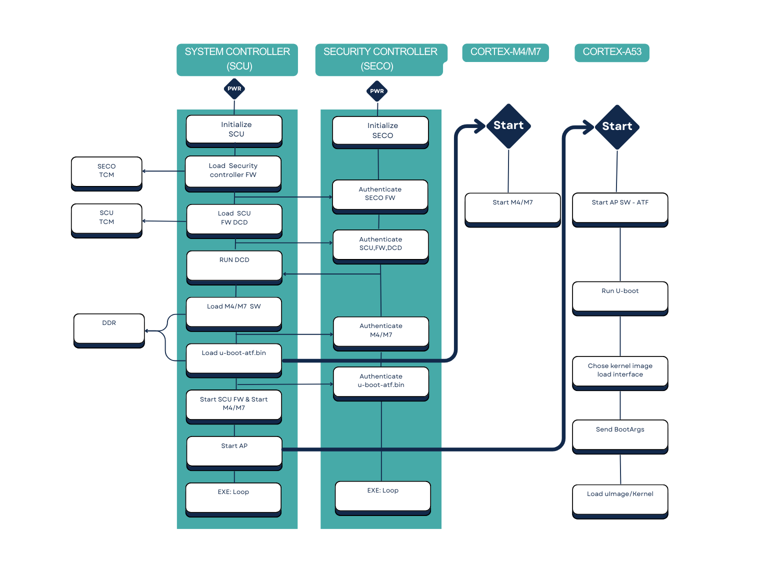
6. Understanding Powering and Booting Sequences
- Before proceeding with customization, comprehensively understand the powering sequence and booting
sequence of the SOC. For NXP hardware, the typical bootup sequence includes:- Power-On Sequence: Sequential power-up of various components to ensure proper initialization and
stability. - Booting Sequence: Initiation of the bootloader, loading of the kernel, and device tree
configuration to bring the system to a functional state.
- Power-On Sequence: Sequential power-up of various components to ensure proper initialization and
By following this approach, you establish a robust foundation for customizing the BSP and integrating it
with the custom hardware design, while simultaneously ensuring adherence to the SOC’s powering and booting
sequences.
					&sai5 {
    status = "okay";
};
DDR and PMIC Configuration
It is essential for any hardware system to initiate the external DDR and PMIC functionalities for proper operation.
For IMX8MM hardware, this initialization process is managed within the U-Boot bootloader, specifically located in the board/freescale/imx8mm_evk/ directory.

The DDR configuration can be adjusted using the RPA tool provided by NXP, tailored for specific DDR vendors.
For PMIC configuration within U-Boot, drivers/power/pmic/pca9450.c is typically involved. However, in the case of imx8qxp hardware, an SCFW (System Controller Firmware) Binary is required for proper functioning.
Once customization is completed, the imx-mkimage tool is employed to generate the flash.bin image file for flashing.
The flash.bin file is a composite image comprising u-boot.bin, SCFW (only applicable for imx8qxp hardware), -ahab-container.img, and m4_image.bin.
Following this, attention turns to the Linux kernel. During the initial stages of kernel bring-up, critical components such as the SOC, memory regions, core kernel, multiple CPUs, clock, and power schemas are imperative.
Starting with the device tree in the kernel, SOC nodes are activated (status=okay), while other nodes, such as peripherals, are deactivated (status=disabled).
Key nodes include SOC, CPU, power schema, memory layout, GPU, and CLK nodes. Additionally, based on schematic analysis, the DEBUG UART node is enabled for logging purposes.

Proceed step by step by examining the device tree for peripherals and pertinent device drivers from the kernel/modules, referencing the config.gz file. In an operational source, adjust configurations using make menuconfig or the defconfig file.
Initially, disable other peripherals. Subsequently, compile the kernel, set up the root filesystem, and prepare for flashing.
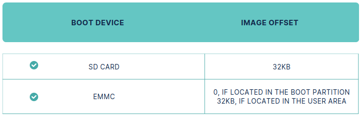
For flashing, leverage the UUU utility. Alternatively, use the dd command for SD card or eMMC Block. Utilize the following offsets for the respective hardware series:
Need expert support for board bring-up, BSP customization, or upstreaming on i.MX8 platforms?
UUU Utility interface
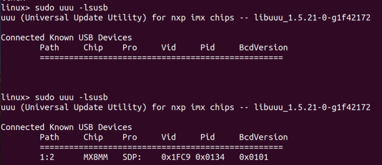
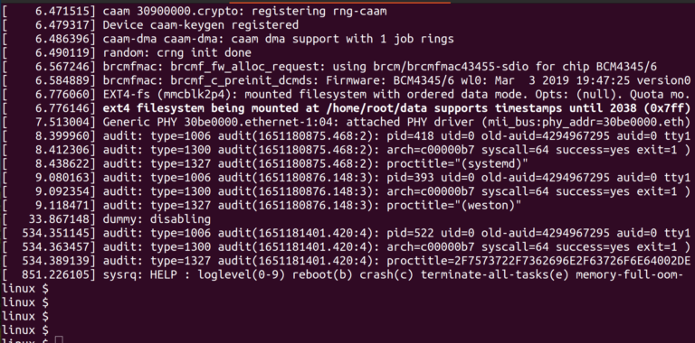
one should see the successful kernel console prompt and can validate that the hardware is now has the life.
During this process, encountering various challenges is common, so here are some debugging tips shared by engineers:
Debugging Tips:
- In Yocto-like build systems, utilize populated SDKs to individually build and customize software components such as U-boot, Linux kernel, and rootfs, thereby optimizing time.
- Employ debugging tools like KGDB, Dmesg, printenv, device tree decompilation tool (DTC), sys entries, and proc entries of important nodes like GPIO and CRO, fdtput, and fw_printenv.
- Utilize the DDR stress test method provided by NXP’s RPA tool to validate DDR configuration.
- Maintain reference logs for analysis and ensure software versions are consistent on both the reference and target sides.
- Ensure firmware is built for the target hardware using an appropriate toolchain setup.
- Ensure sufficient and stable power is available for the hardware to prevent issues.
- Utilize zero-ohm resistors to isolate hardware zones, addressing complexities one at a time.
- Remember to use TP (test point) test points for debugging purposes.
Bottom Line
This article demystifies the unique booting process for i.MX8 family processors, guiding you through hardware and software customizations needed for your custom board. We explore various debugging techniques and tackle common challenges encountered during Embedded System development.
With decades of expertise, Silicon Signals specializes in board bring-up across diverse operating systems including Linux, Android, bare-metal, and QNX. Our proficiency extends to a wide array of platforms such as NXP, Amlogic, Rockchip, Texas Instruments, Xilinx, STM32, and more. For further details, reach out to us at info@siliconsignals.io
