Introduction
Most engineers treat exposure control as a camera feature. It is not. ISP exposure adaptation is an active inference system that runs frame by frame, adjusting sensor parameters in real time to produce images that are usable, not just visible. The difference matters enormously when you are deploying cameras in variable lighting, industrial environments, or AI-assisted inspection lines.
According to a MarketsandMarkets report, the global Image Signal Processor market is projected to reach USD 5.9 billion by 2027, driven by the surge in embedded vision and automotive camera deployments. Behind that growth is a foundational challenge that every camera engineering team faces: getting exposure right, consistently, across the chaos of the real world. That challenge sits squarely inside the ISP pipeline, and it does not get solved without serious ISP tuning services and a deep understanding of how exposure control camera systems actually behave under pressure.
This guide does not restate textbook theory. It explains the mechanics of ISP exposure adaptation from the inside, walks through real-world tuning decisions, and shows where most camera programs break down when they skip professional image tuning services.
How ISP Exposure Adaptation Actually Does
ISP exposure adaptation is the process by which the Image Signal Processor continuously measures incoming light, compares it to a target brightness, and adjusts one or more exposure parameters to bring the image into alignment. The parameters it controls are exposure time (shutter speed), analog gain applied at the sensor level, and digital gain applied after analog-to-digital conversion.
These three parameters are not equivalent. Exposure time determines how long the sensor collects photons. Longer exposure means more light collected, but at the cost of motion blur in dynamic scenes. Analog gain amplifies the signal at the sensor before digitization, introducing thermal noise and shot noise that degrades image quality. Digital gain multiplies the digital signal after conversion, which magnifies noise rather than adding new information.
A well-designed exposure control camera system follows a clear priority hierarchy: maximize exposure time first, then use analog gain conservatively, and treat digital gain as a last resort. When that hierarchy is reversed or ignored, image quality degrades in ways that no downstream processing can fully correct.
This is why ISP exposure adaptation is a design problem, not just a parameter problem. The algorithm driving these decisions must account for sensor characteristics, lens behavior, scene content, and the intended application. A surveillance camera deployed indoors has different convergence requirements than an automotive forward camera approaching a tunnel entrance at highway speed.
The Auto Exposure Feedback Loop
At its core, the ISP exposure adaptation engine runs a closed control loop. Every frame, the ISP collects luminance statistics from the sensor output, most commonly through histogram analysis or a weighted metering grid. It compares the measured brightness distribution against a predefined AE target value. The error between current brightness and target drives a correction signal that modifies exposure time, gain, or both.
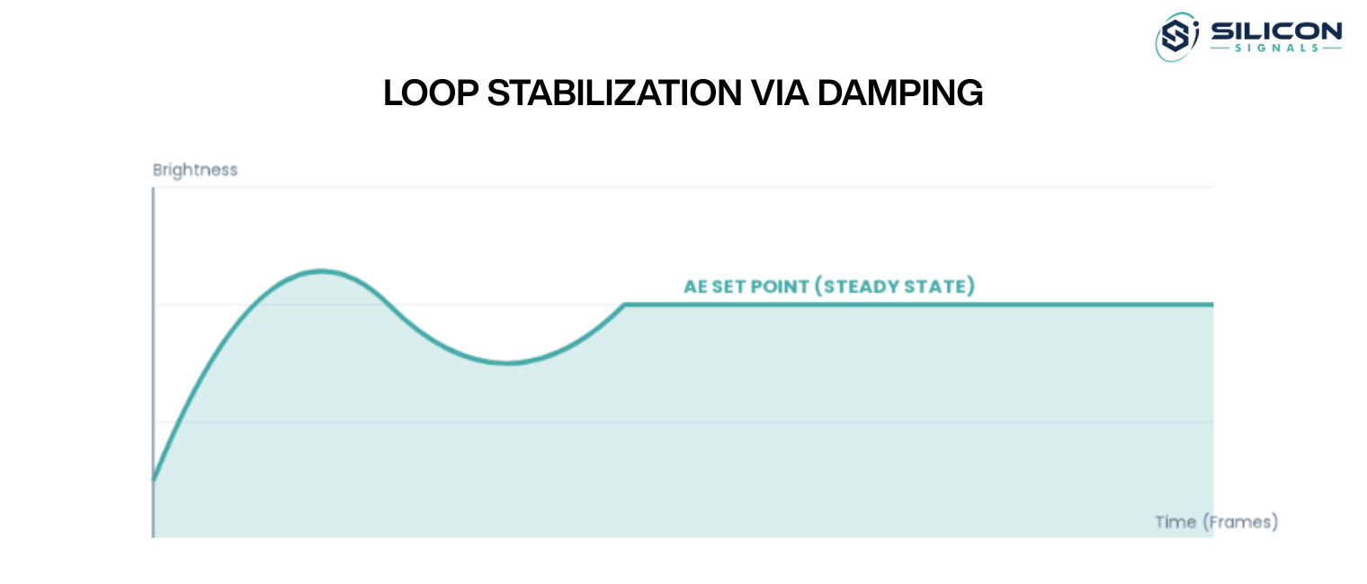
The loop repeats every frame or every few frames depending on the convergence speed setting. Fast convergence responds quickly to lighting changes but introduces instability. In scenes with artificial lighting operating at 50 Hz or 60 Hz, a fast convergence loop without anti-flicker quantization will produce visible brightness oscillations that render footage unusable.
Damping is the mechanism that stabilizes this loop. It limits how aggressively the exposure parameters change from one frame to the next, trading response speed for stability. Getting the damping coefficient right is one of the most common calibration tasks in professional ISP tuning services, and it cannot be determined analytically without real-world validation across target lighting conditions.
The Architecture of Exposure Control Inside the ISP
Understanding ISP exposure adaptation requires understanding where it sits inside the full ISP pipeline. The ISP does not operate on raw sensor data directly. It receives Bayer-patterned data from the sensor, passes it through a demosaicing stage, applies lens shading correction, white balance, noise reduction, and tone mapping before producing the final output image. Exposure adaptation sits at the front of this pipeline because it directly influences sensor integration conditions.
The AE statistics engine typically operates in parallel with the image path. It samples luminance data from a grid of zones across the frame, weights those zones according to the selected metering mode, and feeds the aggregated result to the AE algorithm. The algorithm runs on either the ISP processor itself or a dedicated microcontroller, depending on the hardware architecture.
Metering Modes and Their Trade-offs
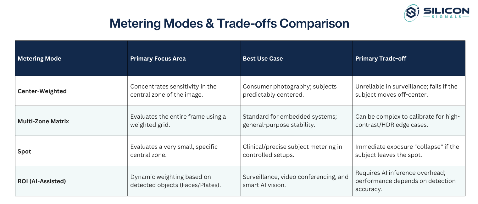
Metering mode selection directly shapes how the exposure control camera responds to scene content. Center-weighted metering concentrates sensitivity in the central image zone. This works well when the primary subject occupies the center frame, which is common in consumer photography but unreliable in surveillance or machine vision applications.
Multi-zone matrix metering evaluates the entire frame using a weighted grid. It produces more stable results across varied scenes and is the standard approach in most embedded camera systems. Spot metering evaluates a very small central zone and is useful for precise subject metering but collapses immediately when the subject moves out of frame.
For AI-assisted applications, region-of-interest metering provides a fourth option. The AI inference engine defines the ROI dynamically based on detected objects, and the ISP exposure adaptation algorithm weights exposure decisions toward that region. This approach solves the backlight compensation problem for face detection cameras without requiring the manual ROI configuration that plagues simpler exposure control camera deployments.
Struggling with Camera Exposure Tuning?
Exposure and Gain Priority Logic
The exposure-versus-gain priority curve defines how the system transitions from increasing shutter speed to increasing gain as the scene darkens. This curve is central to the performance of any ISP tuning services engagement because it encodes the engineering trade-off between motion blur and noise.
In a typical outdoor exposure control camera deployment, the system might allow exposure time to increase up to 10 milliseconds before switching to analog gain. Indoor motion-sensitive applications lower that threshold to 5 milliseconds or less. Industrial inspection systems running at fixed frame rates may lock exposure time entirely and use only gain, accepting noise as a lesser evil compared to motion blur that would invalidate defect detection.
Getting this curve wrong is expensive. Cameras that ramp gain too early produce noisy imagery in conditions where the sensor could capture clean data with longer integration. Cameras that allow excessive exposure time produce motion artifacts that defeat object tracking algorithms. Defining the right curve requires sensor-specific characterization data, which is a core deliverable of professional image tuning services.
Real-World ISP Exposure Adaptation Cases
Theory only goes so far. The real test of ISP exposure adaptation is how it performs in production conditions that combine multiple simultaneous challenges. The following cases reflect actual engineering scenarios encountered during camera system development.
Indoor Surveillance with Mixed Lighting
Indoor environments present three compounding problems for ISP exposure adaptation: mixed light sources with different color temperatures, artificial lighting that oscillates at mains frequency, and wide dynamic range between bright overhead fixtures and shadowed floor areas.
The flicker problem is often underestimated. LED and fluorescent fixtures operating on 50 Hz AC power modulate at 100 Hz. An exposure control camera that sets exposure time independently of this modulation frequency will capture frames at varying phases of the flicker cycle, producing brightness oscillation that appears as visible flicker in the recorded video. The solution is exposure time quantization: constraining allowed exposure times to integer multiples of the modulation period (10 ms for 50 Hz environments, 8.33 ms for 60 Hz environments).
Tuning this system requires anti-flicker configuration at the ISP register level, maximum gain capping to control noise in low-light zones, and an AE target set slightly below the midpoint to retain highlight detail near bright fixtures. This combination of adjustments is exactly what separates empirical ISP tuning services from factory default configurations.

Automotive Camera at High Dynamic Range Transitions
Automotive forward cameras face a specific ISP exposure adaptation challenge that has no consumer camera equivalent: sudden luminance transitions spanning six or more stops of dynamic range. A vehicle entering a tunnel from bright sunlight drops from 100,000 lux to under 1,000 lux in under one second. The reverse transition when exiting is equally abrupt.
Standard AE convergence loops cannot respond fast enough to these transitions without producing frames where either the road surface is completely black or the sky is completely blown out. Multi-exposure HDR addresses this by capturing two or more sub-frames at different integration times within each master frame period, then merging them in the ISP. The exposure control camera produces a single output frame that retains detail in both shadow and highlight regions.
The tuning challenge in HDR automotive cameras is convergence speed for the long-exposure sub-frame. Too slow and the system produces dark frames during tunnel entry. Too fast and the system oscillates in steady-state highway lighting. Region-based metering that weights the road surface above the sky compensates for the inherent luminance asymmetry in forward-facing automotive scenes. All of this requires image tuning services that understand both the physics of automotive lighting and the processing constraints of embedded ISP hardware.
Smart Doorbell and IoT Cameras Under Backlight Conditions
Doorbell cameras face a specific backlight geometry: the subject stands between the camera and an open sky or bright outdoor environment. Standard matrix metering exposes for the background luminance, which places the subject in silhouette. The ISP exposure adaptation system must compensate by biasing exposure toward the subject zone, accepting overexposure in the background to render the subject face correctly.
When AI face detection is available, the inference output can drive a dynamic ROI that updates every few frames as the subject moves. The exposure control camera weights metering exclusively within the detected face bounding box, allowing exposure time and gain to increase until the face region reaches the target brightness. This approach resolves backlight compensation without requiring manual scene-specific calibration and is a primary argument for integrating AI-assisted exposure into the ISP pipeline.
Without AI-assisted metering, IoT camera manufacturers must rely on fixed backlight compensation modes that apply static exposure offsets. These work in predictable geometries but fail when subject position or background luminance varies. The difference between these two approaches illustrates why image tuning services that include AI-ISP co-optimization are increasingly distinct from conventional camera calibration work.

A Practical ISP Tuning Services Guide for Exposure Adaptation
Professional ISP tuning services for exposure adaptation follow a structured process. The steps below reflect what actually works in production camera programs, not what looks clean in an ISP vendor datasheet.
Step One: Define the Exposure Specification Before Touching Parameters
Every ISP exposure adaptation engagement begins with a written exposure specification that defines the target use case. This document captures the luminance range the camera must handle (minimum and maximum lux), the maximum acceptable motion blur (expressed as a maximum integration time in milliseconds), the maximum acceptable noise level (expressed as SNR or noise standard deviation at maximum gain), and the convergence speed requirement (expressed as the maximum number of frames allowed to reach steady state after a lighting step change).
Without this specification, tuning becomes iterative guesswork. With it, every parameter decision connects to a verifiable requirement. This is the foundation of structured image tuning services that produce cameras that pass validation on the first attempt rather than the fifth.
Step Two: Characterize the Sensor Before Configuring the ISP
Sensor characterization provides the empirical data that exposure algorithms require. This includes measuring read noise at each gain setting, quantifying the full-well capacity, determining the actual response curve (which deviates from the nominal specification in production units), and identifying any fixed-pattern noise sources that interact with gain settings.
This characterization data directly informs where the exposure priority curve transitions from shutter speed to gain. A sensor with low read noise at 8x gain can use that gain conservatively without visible image degradation. A sensor that shows significant fixed-pattern noise at the same setting requires the exposure control camera system to prefer longer integration times even at the cost of mild motion blur.
Step Three: Configure the AE Loop Parameters
Once the sensors have been characterized, setting the parameters of the AE loop is now assured. The target for the AE system determines the desired level of brightness. For applications involving surveillance and embedded vision, a target value that is somewhere between 45% and 55% of the maximum possible histogram brightness works best, allowing sufficient leeway in highlights without sacrificing shadow detail. In situations where there are constant bright spot light sources, it is best to use a lower target value.
Convergence damping is set based on the convergence speed requirement from the exposure specification. The ISP tuning services engineer adjusts damping until the step response meets the convergence frame count requirement without producing overshoot or oscillation in the steady-state response.
Step Four: Validate Against Real Lighting Conditions
Lab validation with controlled light sources is insufficient for production camera qualification. ISP exposure adaptation tuning must be validated against the actual lighting conditions the camera will encounter in deployment: flicker from specific luminaire types, directional backlight from target architectural geometries, the specific dynamic range transitions present in the deployment environment.
Real-world validation frequently reveals interactions between ISP exposure adaptation and other ISP pipeline stages that lab testing misses. Noise reduction algorithms interact with gain settings in ways that affect AI inference accuracy. Tone mapping curves affect the apparent brightness that the AE statistics engine reports, creating feedback effects that only appear at specific scene luminance levels. These interactions require the tuning engineer to iterate across the full pipeline, not just the AE configuration. This is exactly the scope of work delivered by comprehensive image tuning services engagements.
Where ISP Exposure Adaptation Programs Break Down
Camera programs fail at ISP exposure adaptation for predictable reasons. Understanding these failure modes helps engineering teams avoid them.
Gain Priority Inversion
The most common mistake is allowing the system to ramp analog gain before maximizing exposure time. This happens when the default gain priority curve from the ISP vendor is applied without modification. Vendor defaults optimize for convergence speed rather than image quality. The result is an exposure control camera that produces noisy images in low-light conditions where a properly tuned sensor would still deliver clean frames at longer integration times.
Anti-Flicker Misconfiguration
Deploying a camera without validating anti-flicker configuration for the target environment is a common oversight that produces defective footage. A camera configured for 60 Hz anti-flicker deployed in a 50 Hz market (or vice versa) will produce visible brightness oscillation in all indoor footage. Professional ISP tuning services include anti-flicker validation as a standard deliverable because the cost of fixing this in production is disproportionate to the cost of getting it right during development.
Missing ROI Integration
Applications that include AI inference for object detection or face recognition frequently deploy the AI output and the ISP exposure adaptation system as independent subsystems. The AI detects objects. The exposure system meters the global scene. Neither informs the other. The result is correct inference results in good lighting and collapsed inference accuracy in backlit or low-contrast scenes where exposure control camera settings are not optimized for the region that matters.
Closing this loop requires an architecture decision made early in the camera system design. Once the firmware is in production, adding ROI-based metering to an ISP exposure adaptation pipeline is expensive and disruptive. It is the kind of structural decision that experienced image tuning services teams flag during architecture review rather than after integration testing.
Building a High-Performance Camera Product?
How a Camera Design Company Integrates ISP Exposure Adaptation Across the Development Lifecycle
ISP exposure adaptation does not exist in isolation from the rest of the camera system. How well it performs depends on decisions made at every stage of camera development, from sensor selection through firmware architecture to production calibration.
Hardware Design and Sensor Selection
The exposure performance envelope of any exposure control camera is determined before firmware is written. Sensor selection defines the read noise floor, the full-well capacity, the dynamic range, and the gain architecture. A sensor with a poorly implemented analog gain chain will produce fixed-pattern noise that no amount of ISP exposure adaptation tuning can eliminate. Lens selection determines the minimum f-number and therefore the maximum light throughput at zero gain.
A camera design company evaluating sensors for a new product must assess datasheet claims against measured performance. Nominal specifications for read noise and dynamic range frequently differ from measured performance in production silicon. The characterization data gathered during sensor evaluation directly seeds the ISP tuning services work that follows.
Firmware Architecture and BSP Development
The ISP exposure adaptation algorithm runs inside firmware, either in the ISP hardware block or in software running on the application processor. How it is implemented determines whether it can be modified, validated, and updated in the field. Firmware that hard-codes AE parameters without a calibration interface forces hardware rework to change exposure behavior, which is unacceptable in production programs.
Board Support Package development for an exposure control camera platform must include sensor driver implementation that exposes the full integration time and gain register interface to the ISP, timing synchronization between the sensor frame cycle and the ISP statistics collection period, and a calibration data loading mechanism that applies sensor-specific tuning at boot time.
AI Integration and ISP Co-optimization
Modern camera products increasingly run neural network inference on the same SoC that hosts the ISP. Integrating the AI output into ISP exposure adaptation requires a software interface between the inference engine and the AE control loop. This interface must operate with sufficiently low latency that the ROI reported by the AI reflects the current frame rather than a frame that is several exposure cycles stale.
For applications where inference accuracy is the primary system requirement, optimizing the exposure control camera for AI performance rather than human-perceptible image quality produces measurably better results. This means tuning AE targets and convergence parameters against inference accuracy metrics, not against visual quality scores. The image tuning services scope for these applications includes AI-in-the-loop validation that connects exposure parameter choices directly to inference performance data.
Validation and Production Calibration
Production calibration for ISP exposure adaptation generates per-unit calibration data that compensates for sensor-to-sensor variation in dark current, fixed-pattern noise, and gain accuracy. Without this step, exposure behavior varies across units in ways that cause field quality issues at scale. The production calibration procedure must be designed during development, not retrofitted after manufacturing begins.
This is where integrated ISP tuning services and production engineering expertise intersect. The calibration procedure must be fast enough to be economically viable at production throughput, accurate enough to produce consistent exposure behavior across units, and robust enough to run in a manufacturing environment without specialized optical equipment.
Conclusion
ISP exposure adaptation is not a component that ships working and stays working. It is an engineered behavior that must be specified, characterized, tuned, validated, and maintained across the full camera development lifecycle. Every decision from sensor selection to production calibration affects how the exposure control camera performs under real-world conditions.
The failure modes are well understood. Gain priority inversion, anti-flicker misconfiguration, and the absence of AI-ISP integration account for the majority of exposure quality issues in production camera programs. These failures share a common root cause: treating ISP exposure adaptation as an isolated tuning task rather than a system-level design problem.
Professional image tuning services address this by treating exposure adaptation as part of the camera system, not apart from it. The tuning engineer who understands sensor physics, ISP pipeline interactions, AI inference requirements, and production calibration economics produces fundamentally different outcomes than one who adjusts AE parameters in a controlled lab environment and calls the work done.
Silicon Signals is a camera design company that builds and tunes complete camera systems for embedded vision, industrial inspection, and AI-enabled applications. Their work spans hardware design, BSP and firmware development, AI-ISP integration, and production-ready ISP tuning services. If your camera program is encountering exposure quality issues, convergence failures, or AI-ISP integration challenges, Silicon Signals has the engineering depth to diagnose and resolve them across the full stack.
